

Description

Dimensions
| d | 30 mm | Bore diameter |
|---|---|---|
| D | 55 mm | Outside diameter |
| B | 19 mm | Width |
| d1 | ≈ 40 mm | Shoulder diameter inner ring |
| D1 | ≈ 45 mm | Shoulder diameter outer ring |
| E | 49.6 mm | Raceway diameter outer ring |
| s | max. 2 mm | Permissible axial displacement from the normal position of one bearing ring relative to the other |
| r1,2 | min. 1 mm | Chamfer dimension |
| r3,4 | min. 0.3 mm | Chamfer dimension |
| Parameter r3.4 has either the value specified here or the same value as r1.2. |

Abutment dimensions
| da | min. 35 mm | Abutment diameter shaft |
|---|---|---|
| das | 37.8 mm | Abutment diameter shaft |
| Da | max. 50 mm | Abutment diameter housing |
| Db | max. 52 mm | Abutment diameter housing |
| ra | max. 1 mm | Fillet radius |
| rb | max. 0.3 mm | Fillet radius |
Calculation data
| Basic dynamic load rating | C | 39.6 kN |
|---|---|---|
| Basic static load rating | C0 | 44 kN |
| Fatigue load limit | Pu | 5 kN |
| Reference speed | 6 000 r/min | |
| Limiting speed | 7 500 r/min | |
| Calculation factor | kr | 0.3 |
| Limiting value | e | 0.3 |
| Calculation factor | Y | 0.4 |
Tolerances and clearances
General bearing specifications
- Tolerances: Normal
- Radial internal clearance: table
Bearing interfaces
- Seat tolerances for standard conditions
- Tolerances and resultant fit
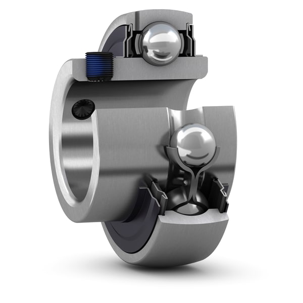
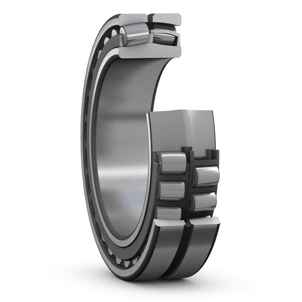
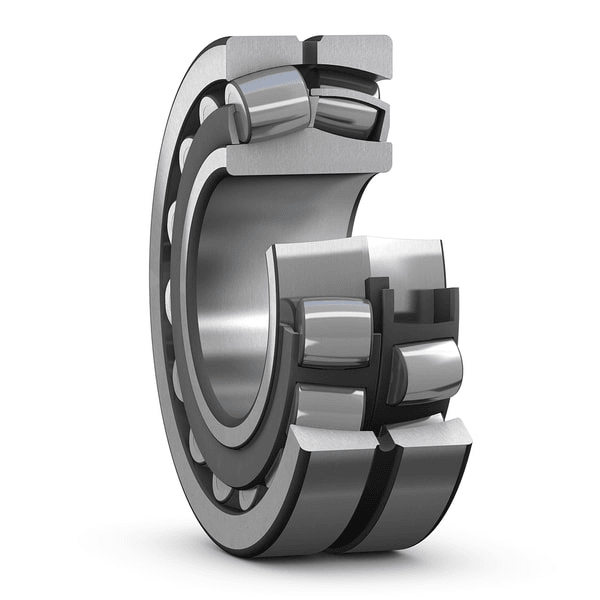
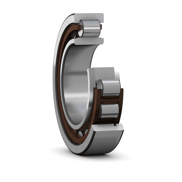
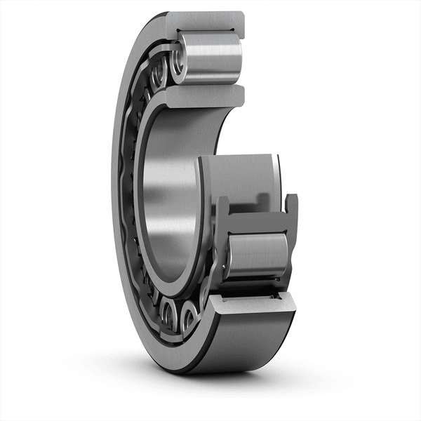
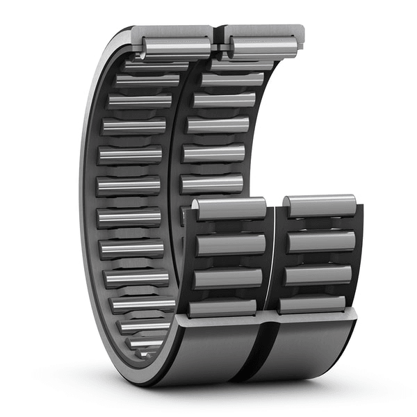
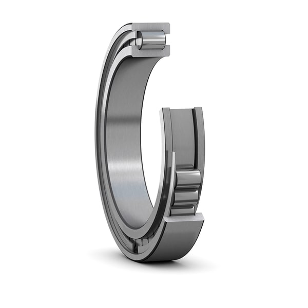
Single row full complement cylindrical roller bearings are designed to accommodate very high radial loads in combination with moderate speeds. The bearings incorporate a maximum number of rollers as they are not equipped with a cage. Having two integral flanges on the inner ring and one flange on the outer ring, NCF design bearings can accommodate axial displacement in one direction. A retaining ring on the outer ring holds the bearing together. The retaining ring should not be loaded axially during operation.
- Very high radial load carrying capacity
- High radial stiffness
- Long service life
- Locate the shaft axially in one direction